|
|
The Optimize Phase Speaker sub menu includes tabs for Power Shading, Application, Edit, Input EQ, and Dynamic EQ. Refer to Design Phase - Speakers for details about Power Shading and Application tabs. The Edit, Input EQ, and Dynamic EQ tab features are described below and offer a granular level of control for advanced and specific requirements.

The features detailed below covering the Edit, Input EQ, and Dynamic EQ tabs include a number of EQ panel menus. These menus function similarly to the EQ menus as seen in the Optimize Phase - EQ. The descriptions below detail the unique features of each of these menus and assume a familiarity with the basic use of EQ panel tools, charts, and adjustments.
Follow the links below to jump to the topics covered on this page:
Limiters - Threshold, Side Chain EQ RMS, Side Chain EQ Peak
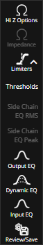
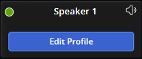
Use the Edit Profile button on a speaker device to access the advanced speaker options control panel.
Hi Z Options panel is divided into 70 Volts Taps and 100 Volts Taps. This option isn't available when a speaker is in Low Z mode.

Power: Select the first checkbox to unlock the editable text field for Power. Each checkbox and text field becomes available once the line above it has been selected. The Power value of the first line is set automatically but may be edited. Each subsequent line selected will have a power value set to half of the proceeding line. Changing the value of a line will automatically update the value of each line after to half of the selected value but will not change the value of each line before it. Power is displayed in Watts.
Impedance: Once the checkbox is selected for a line the impedance value will be made visible. The text field is not directly editable but will automatically adjust to changes made to the Power text field on the same line or a line above. For Example, editing the Power value of line 3 will update the Power and Impedance for lines 4 and 5 but lines 1 and 2 will remain unchanged. Impedance is displayed in ohms.
Many of the features detailed below overlap with the options available in the Deploy Phase - Impedance action. See that section for additional information on specific options available there.
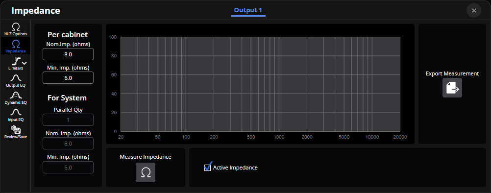
Per Cabinet Nom.Imp.: Adjust the Per Cabinet Nominal Impedance value to change the average impedance presented to an amplifier (range 2.6 - 999.0 ohms).
Per Cabinet Min Imp.: Adjust the Per Cabinet Minimum Impedance value to change the lowest impedance presented to an amplifier (range 2.6 - 999.0 ohms).
Parallel Qty: View the parallel quantity of the system.
For System Nom.Imp.: For System Nominal Impedance represents the overall impedance presented.
For System Min Imp.: For System Minimum Impedance represents the combined minimum impedance presented.
Measure Impedance: Triggers a diagnostic sweep, sends a test signal across the full frequency range to the connected speaker and precisely measures its electrical response, creating a detailed impedance curve that is displayed on the panel menu chart.
Active Impedance: Check to display the results of the most recent measurement performed via the Measure Impedance button. It represents the speaker's current, real-time electrical state.
Export Measurement: Export the Active Impedance data to a file on an external device.
Each of the three limiters tabs is editable per channel, the channel number tab is selectable along the top edge of the panel menu.
Thresholds panel is divided into Recommended Amp Power and Limiter Settings sections. The Recommended Amp Power fields are further divided into Per Cabinet and Per Channel columns. Limiter Settings are split into Thermal and Zero Overshoot columns.
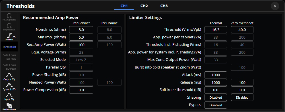
Nom.Imp.: Adjust the Per Cabinet Nominal Impedance value to change the average impedance presented to an amplifier (range 2.6 - 999.0 ohms). Per Channel Nominal Impedance represents the overall impedance presented.
Min Imp.: Adjust the Per Cabinet Minimum Impedance value to change the lowest impedance presented to an amplifier (range 2.6 - 999.0 ohms). Per Channel Minimum Impedance represents the combined minimum impedance presented.
Rec. Amp Power: Set the Per Cabinet Recommended Power value to match the power range that a single loudspeaker cabinet is designed to handle (range 0 - 7000 watts). Per Channel Recommended Power value displays the total power handling capacity of the system. This field is not adjustable while in Hi-Z mode.
Equi. Voltage: Equivalent Voltage is displayed in Vrms (Root Mean Square Volts) and this value translates the recommended power into a voltage specification based on the speaker's impedance.
Selected Mode: The selected mode is displayed.
Parallel Qty: The Parallel Quantity value for the selected speaker is displayed.
Power Shading: The Power Shading value for the selected speaker is displayed.
Needed Power: Per Cabinet Needed Power is displayed in watts and can be used to determine how much power is needed to supply the to the speaker. Per Channel Needed Power displays how much power, in watts, needs to be delivered by the amplifiers to maintain the desired audio output level across all speakers.
Power Compression: Adjust this value to set the power compression value in decibels (range -20 - 0.0 dB).
Limiter Threshold settings are not adjustable while in Hi-Z mode.
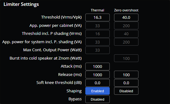
Threshold: The Thermal Threshold field is editable with a range of 1.0 - 999.0 root-mean-square voltage (Vrms). The Zero Overshoot Threshold field is also editable with a range of 1.0 - 999.0 peak voltage (Vpk).
App. power per cabinet: Both App Power per cabinet fields, Thermal and Zero Overshoot, are displayed in Volt-Amps (VA) and automatically adapt to fit with values selected for Low Z Data and Limiter Settings.
Threshold incl. P shading: Both Threshold including Power Shading fields, Thermal and Zero Overshoot, are displayed as root-mean-square voltage (Vrms) and automatically adapt to fit with values selected for Low Z Data and Limiter Settings.
App. power for system incl. P. shading: Both Application Power for System including Power Shading fields, Thermal and Zero Overshoot, are displayed in Volt-Amps (VA) and automatically adapt to fit with values selected for Low Z Data and Limiter Settings.
Max Cont. Output Power: The Max Output fields are displayed in Watts and automatically adapt to fit with values selected for Low Z Data and Limiter Settings.
Burst into cold speaker at Znom: The Burst into Cold Speaker at nominal impedance (Znom) field is displayed in Watts and automatically adapts to fit with values selected for Low Z Data and Limiter Settings.
Attack: Sets the time it takes for the output level attenuation to activate once the input level exceeds the threshold. This is an editable field with a range of 1 - 35000 milliseconds (ms).
Release: Sets the time it takes for the level attenuation to deactivate once the input level drops below the threshold. Both Thermal and Zero Overshoot fields are editable with a range of 1 - 35000 milliseconds (ms).
Soft knee threshold: Defines the smoothness of the transition from one compression ratio to another. Both Soft Knee Threshold fields, Thermal and Zero Overshoot, are editable with a range of -6.0 - 0.0 decibels (dB).
Shaping: Each limiter has a Side Chain EQ (RMS and Peak) tab that is accessible while the Thermal or Zero Overshoot Shaping toggles are enabled.
Bypass: Use bypass to ignore these settings without changing them. Bypass is disabled by default.
Side Chain EQ Root Mean Square is editable per output channel, the channel number tab is selectable along the top of the panel menu for devices with multiple channels. This panel includes a 4-band EQ Filter Chart and Filter Adjustment menu. See Optimize EQ for details on these features.
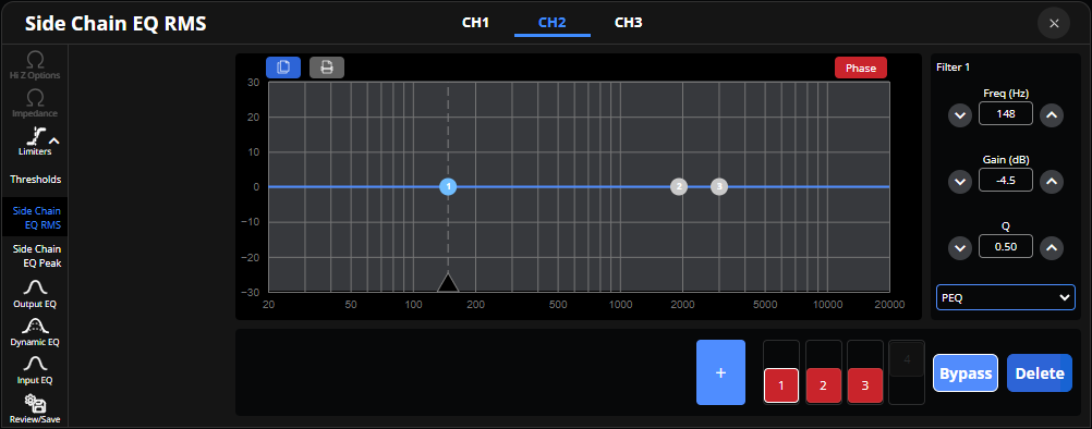
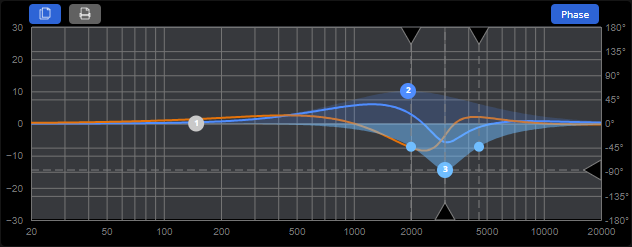
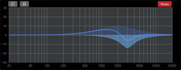
Phase Toggle: The Phase toggle will display the curve of the phase response of the audio signal across different frequencies in relation to the Side Chain EQ RMS curve.
Side Chain EQ Peak is editable per output channel, the channel number tab is selectable along the top of the panel menu. This panel includes a 4-band EQ Filter Chart and Filter Adjustment menu. See Optimize EQ for details on these features.
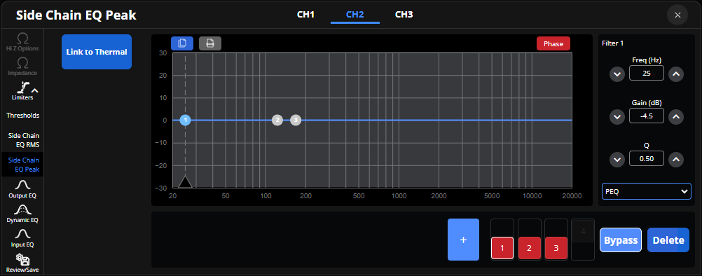
Link to Thermal: Select this toggle to have the Side Chain EQ Peak chart copy the curve of the Side Chain EQ RMS. While linked, the band and filter controls, and level adjustments, will be unavailable.
Output EQ is editable per output channel, the channel number tab is selectable along the top of the panel menu. The first two bands cannot be deleted and are intended to be used as a crossover, and thus allow a greater slope than other bands. This panel includes a Speaker Adjustment menu, EQ Filter Chart, and Filter Adjustment menu. See Optimize EQ for details on these features.
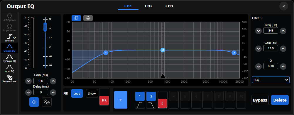
FIR: The Voltera FIR filter options include a load button to open the file explorer and select a file, a show toggle, and a FIR activation toggle.

Output Labels: Each output field is used for changing output label names. (Up to 8 characters)
Lock: Provides options to lock or hide specific information within the Loudspeaker Customization Panel menu. A locked section is presented in a read only state whereas a hidden section keeps fields blocked from view. Once a correct password has been accepted in the type line under Security, each section may be locked or unlocked and may be made visible or hidden. While a loudspeaker section is locked or hidden, no changes may be made.
Info: Includes editable fields for Brand, Family, Line, Model, and Application as well as a Speaker Type drop-down menu. This section also includes a version number display and a text field for writing notes about the device.
Security: If a password hasn't been set, the Security section includes two text fields for setting a password and confirming that password. Both fields must match to set a password. If a password has been set, a single text field for typing the password to unlock is available instead. Save As, saves current values to a newly created file. Save, saves current values to an existing file.
Access the Input EQ panel by clicking on the interactive button on the virtual device. Changes made to the Input EQ chart will be reflected in the graph on the interactive button.

This panel includes a Speaker Adjustment menu, EQ Filter Chart, and Filter Adjustment menu. See Optimize EQ for details on these features.
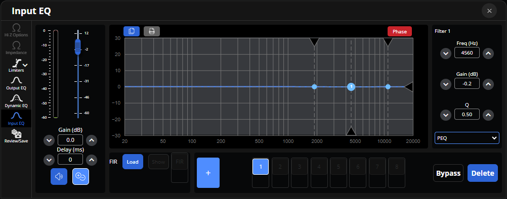
FIR: The Voltera FIR filter options include a load button to open the file explorer and select a file, a show toggle, and a FIR activation toggle.
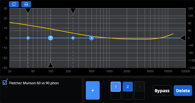
Access the Dynamic EQ panel by clicking on the interactive button on the virtual device. Changes made to the Dynamic EQ chart will be reflected in the graph on the interactive button.
Dynamic EQ includes Pre, Selected Filter, and Post meters. This panel includes a 3-band EQ Filter Chart, See Optimize EQ for details on this feature. This also includes Filter Adjustments for Threshold (dBu), Frequency (Hz), Gain (dB), and Q for each band.
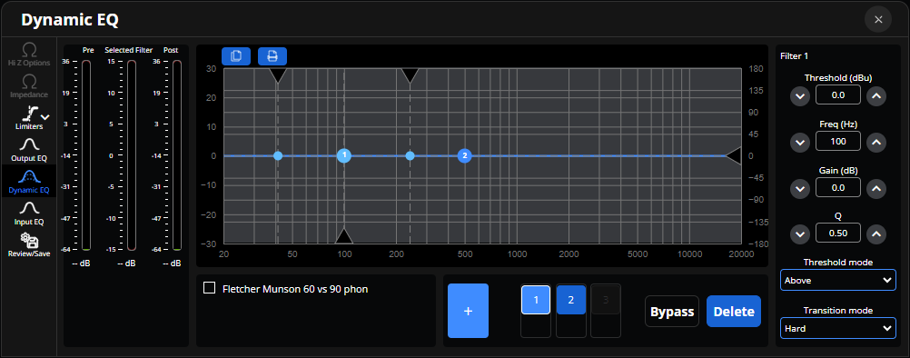
Threshold Mode: Dynamic processing may be set to happen before or after reaching the threshold value. If the band is set to activate when the signal exceeds the threshold value, there will be no processing when the signal is lower than the threshold value. If the band is set to activate when the signal is lower than the threshold value, there will be no processing when the signal exceeds the threshold value.
Transition Mode: Sets how the transition between the non-compression and compression states is made. The Hard setting indicates a quick switch to compression as soon as the signal level exceeds the threshold value. The Soft setting indicates a softer and slower transition to compression when the threshold is exceeded.
Fletcher Munson: Select the checkbox to compare the Dynamic EQ curve with the 60 vs 90 phon equal-loudness contour.